Porosity and Slag Issues in Vacuum Die-Cast Aluminum Shock Towers: Analysis and Solutions
Problem: Shock Tower Mechanical Properties Fall Short
Aluminum alloy shock towers, critical load-bearing components in new energy vehicles (NEVs), demand high yield strength (≥150 MPa) and elongation (as-cast ≥5%) to ensure safety in complex, thin-walled designs. However, initial trials of a shock tower (532×365×299 mm, ~3 mm wall thickness, 4.043 kg) for an OEM revealed uneven mechanical properties, with elongation dipping as low as 1.78% in some areas—well below the 5% target. This jeopardizes stable mass production. Defect analysis pinpointed porosity and slag inclusions as the culprits. How can vacuum die-casting overcome these flaws?
Approach: From Performance Testing to Defect Root Cause
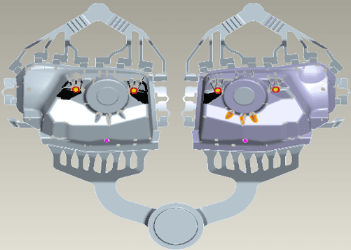
To diagnose the issue, we sampled the casting body at key locations (see Fig. 1): near-gate (No. 5), far-gate (No. 1), mid-section (Nos. 2-4), and flow-transition zones (Nos. 6-7). Mechanical properties were tested using a WDW3200 tensile tester (2 mm/min rate), while microstructure and fracture surfaces were examined via an OLYMPUS GX51 metallographic microscope and JEOL JSM6480 scanning electron microscope (SEM).
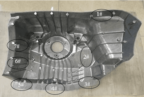
Alt: Sampling positions on vacuum die-cast aluminum shock tower
Performance Results
- Tensile Strength: Nos. 2, 3, 4 averaged above 265 MPa (peak 271 MPa); others fell below 250 MPa (low 247.5 MPa).
- Yield Strength: Consistent at ~150 MPa across all, with variance ≤7 MPa.
- Elongation: Nos. 2, 3, 4 averaged ~8% (peak 9.11%); others ~4%, with No. 1 at 1.78%.
Defect Insights
- Microstructure: Grain sizes uniform (α-Al + eutectic phases), but Nos. 1, 5, 6 showed pores (10-50 μm), while No. 3 had none (see Fig. 2).
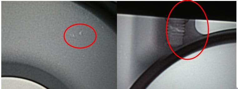
- Fracture Morphology: No. 3 showed quasi-cleavage with dimples and tear ridges (eutectic Si + AlMnFeSi phases); Nos. 1, 5, 6 revealed pores and slag, with Nos. 6, 7 showing random pore sizes (see Fig. 3).
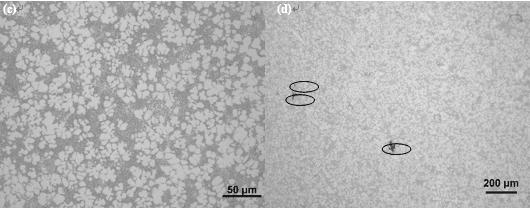
Alt: Porosity and microstructure in shock tower samples

Root Causes
- No. 1 (Far-Gate): Last to fill, lower melt temperature, trapping residual gas and slag—highest porosity.
- No. 5 (Near-Gate): Narrow runner created a flow dead zone, retaining gas and slag.
- Nos. 6, 7 (Transition Zones): Sharp 90° flow shift and insufficient melt supply caused turbulence and gas entrapment.
Porosity stemmed from high melt gas content, poor venting, or suboptimal parameters; slag linked to inadequate refining and flow dead zones.
Methods: Targeted Process and Mold Improvements
Based on the analysis, we implemented these fixes:
- Widen No. 5 Runner: Enlarged to ensure smooth sidewall filling, minimizing dead zones.
- Expand No. 1 Slag Trap: Increased size to capture slag and gas at the far-gate.
- Enhance Melt Degassing: Raised melt temperature to 690-700 ℃ with intensified refining to cut gas content.
- Boost Vacuum Level: Improved mold sealing, reducing cavity pressure to ≤5×10³ Pa (from 9×10³ Pa).
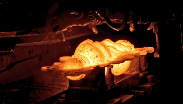
The trial used an IDR3500T die-casting machine with a two-cavity layout. Key parameters: 1250 mm shot sleeve, 29.64% fill ratio, 680-700 ℃ melt temperature, mold temperature ≥200 ℃ (see Fig. 4).
Alt: Improved gating system for vacuum die-cast shock tower
Conclusion: Significant Performance Gains
Post-improvement results (Table 1) showed marked gains:
| Location | Tensile Strength (MPa) | Yield Strength (MPa) | Elongation (%) |
|---|---|---|---|
| 1 | 284 | 152 | 7.13 |
| 2 | 290 | 150 | 8.25 |
| 3 | 295 | 151 | 8.40 |
| 4 | 288 | 149 | 8.10 |
| 5 | 286 | 153 | 7.90 |
| 6 | 285 | 150 | 7.95 |
| 7 | 287 | 152 | 8.05 |
- Tensile Strength: Minimum rose to 284 MPa (up 26% from 225 MPa).
- Elongation: Minimum hit 7.13% (up 100% from 3.56%), all exceeding 5%.
- Yield Strength: Stable at ~150 MPa.
Porosity and slag dropped sharply, yielding uniform properties. This validates that optimizing the gating system, melt quality, and vacuum level effectively tackles defects in complex thin-walled parts, paving the way for reliable “steel-to-aluminum” transitions in mass production.