Optimized Die Casting Mold Design for Aluminum Alloy Lower Cylinder Block in Automotive Engines
Principles: The Critical Role of High-Performance Die Casting Molds
The lower cylinder block, a vital engine component, directly impacts performance and vehicle lightweighting. Aluminum alloys, with their low density, high strength, and excellent castability, are ideal for this application. However, the complex structure of the lower cylinder block—featuring variable wall thickness, integrated cast iron inserts, and stringent oil passage requirements—demands advanced mold design. Optimization must address poor melt flow, internal defects (e.g., porosity, shrinkage), and core durability to ensure part quality and production efficiency.

Problem: Technical Challenges in Lower Cylinder Block Die Casting
A new lower cylinder block (390 mm × 350 mm × 170 mm, average wall thickness 7 mm, weight 6.05 kg, A380 alloy) integrates five cast iron inserts and high-precision oil passages, posing significant casting challenges:
- Uneven Wall Thickness and Flow Issues: Wall thickness ranges from 2 mm (thin areas) to 22 mm (thick areas), causing uneven mold temperatures and hindering melt flow and feeding.
- Insert Separation Risk: Five cast iron inserts (total weight 7.41 kg) must bond seamlessly with aluminum, but temperature differences and misalignment risk detachment.
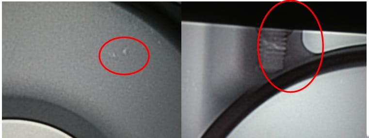
- Internal Defects: The filter mounting surface and oil passages require leakage rates below 2 mL/min at 0.29 MPa, yet gas entrapment and shrinkage occur in thick sections.
- Core Damage: The core for oil passage II, facing high-speed melt impact, is prone to fracture or burn-in, reducing mold life.
Conventional mold designs struggle to meet these demands, necessitating targeted improvements.
Approach: Optimized Mold Design Solutions
1. Gating System Enhancements
To prioritize quality at the filter surface and oil passages, a falcon-beak single-side gating system is adopted (see Figure 1). This directs melt smoothly to the moving mold side’s base, reducing turbulence and aiding gas expulsion. Simulation (see Figure 2) confirms smooth filling from the moving to fixed mold side, meeting design goals. A 2 mm high, 2 mm wider anti-collapse boss at the sprue (see Figure 3) prevents material chipping. An overflow and exhaust system with toothed chill vents at four zone ends (see Figure 4), paired with vacuum assistance, reduces porosity to below 0.15%, addressing gas entrapment at thick-thin junctions.
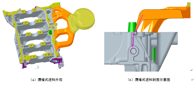
Figure 1: Falcon-Beak Gating Structure Diagram, Optimizing Melt Flow Direction
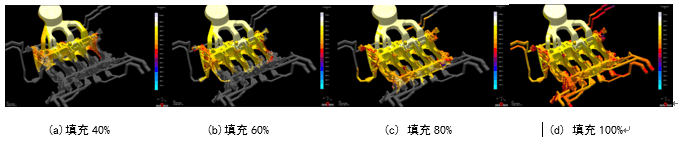
Figure 2: Filling Simulation of Fixed and Moving Mold Sides, Validating Smooth Filling
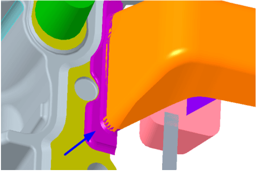
Figure 3: Falcon-Beak Gating Structure anti-collapse boss at the sprue
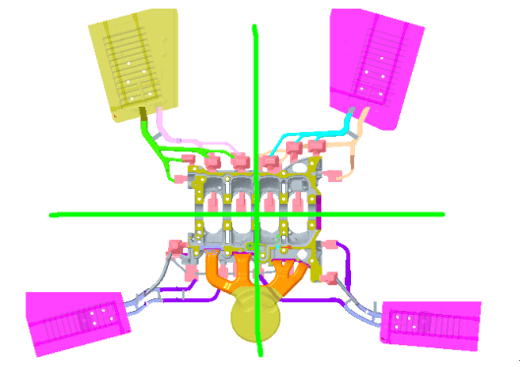
Figure 4: An overflow and exhaust system with toothed chill vents at four zone ends
2. Cast Iron Insert Installation Optimization
Five cast iron inserts are positioned on the fixed mold side via through-holes (0.17 mm unilateral clearance, conical guide), with moving mold side cores inserting 2 mm deep (0.025 mm clearance, see Figure 5). Preheated to 230 ℃, inserts align with mold temperatures (150-200 ℃ post-spraying), preventing separation due to thermal mismatch. Trials confirm robust bonding without looseness or cracks.
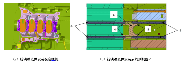
Figure 5: Cast Iron Insert Installation Diagram, Showcasing Positioning and Fit Design
3. Solutions for Shrinkage and Core Issues
- Oil Passage I Extrusion Design: A Φ12 mm extrusion pin (20 mm stroke) with a Φ80 mm cylinder and cooling plate (see Figure 6) targets the 22 mm thick section, eliminating shrinkage. The resulting ring is machined off, ensuring internal integrity.
- Oil Passage II Core Reinforcement: YXR33/W360 high-toughness material (HRC 52-54) with Dura-AR plasma treatment (HV 3600) and a Φ6 mm ultra-chilled hole (1.5 MPa water pressure, see Figure 7) enhances impact resistance and heat durability, minimizing burn-in.
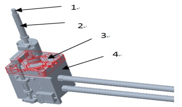
Figure 6: Extrusion Structure Diagram, Showcasing Shrinkage Solution
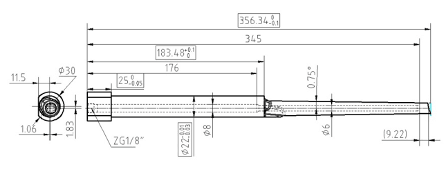
Figure 7: Oil Passage II Core Design Diagram, Enhancing Durability
Summary: Design Outcomes and Practical Value
The optimized mold design markedly improves casting quality:
- Improved Formability: Falcon-beak gating and zoned exhaust reduce porosity to <0.15%, with no surface defects post-machining.
- Internal Quality Compliance: Extrusion and ultra-chilling eliminate shrinkage, achieving oil passage leakage <2 mL/min.
- Production Stability: Reliable insert installation and extended core life, with minor cooling adjustments resolving cold shuts at the tail.
Trials on a UBE 16500 kN machine with the parameters below (Table 1) yielded stable results, meeting technical standards post-machining. This design offers a practical blueprint for mass-producing complex aluminum lower cylinder blocks, advancing engine lightweighting.
Table 1: Die Casting Trial Parameters
| Parameter | Value |
|---|---|
| Chamber Length | 760 mm |
| Slow Speed | 0.2 m/s |
| High Speed | 4.5 m/s |
| Injection Pressure | 58 MPa |
| Dwell Time | 22 s |
| Melt Temperature | 650 ℃ ±10 ℃ |