Die-Casting Porosity Solutions: Developing a Multi-Cavity Mold for Small Brackets
Principles of Small Bracket Die Casting
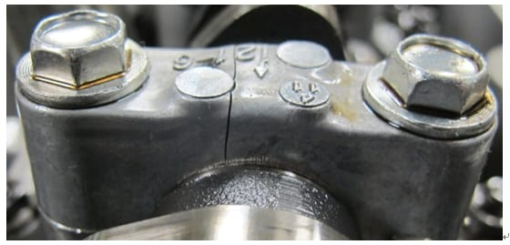
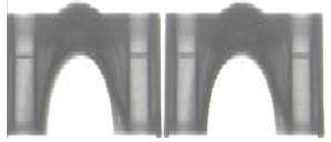
Small brackets in automotive engines support moving parts like camshafts and driveshafts. Typically split into an upper cap and lower body, each with a semicircular arc, they’re assembled and bored together to house bearings. With lightweight design trends, these brackets now use die-cast aluminum alloys (e.g., ADC12) instead of steel, weighing 20-50 grams for easier assembly. See Figure 1 for a typical shape.
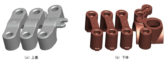
The upper cap requires machining on one mating surface and two dowel holes, while the lower body, linking to the engine block, needs two mating surfaces and four dowel holes. The semicircular bore is finished post-assembly at the engine plant.
The Problem: Die-Casting Defects in Small Brackets
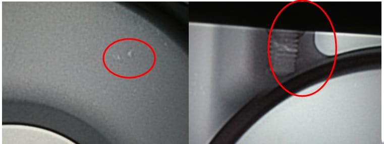
Small bracket molds are simple, often using a slider-free split design. However, uneven wall thickness leads to shrinkage porosity in thicker areas (see Figure 2).
Supporting rotating shafts under load and vibration, these brackets demand high internal quality, meeting the #2 standard in Figure 3.
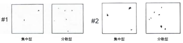
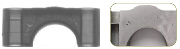
Excessive internal voids can cause fractures during use, risking engine failure. Figure 4 shows a bracket cracking in an endurance test due to a 0.15% porosity rate—well beyond limits.
Approach: Optimizing the Gating System
Small brackets are produced in multi-cavity molds on horizontal cold-chamber die-casting machines. To tackle porosity, the gating system must balance filling across cavities. Traditional methods rely on symmetrical runners or trial-and-error gate adjustments, but these extend development time and wear molds. Numerical simulation (e.g., ProCAST) offers a faster, more precise way to design balanced multi-cavity gating systems.
Feeding Method Selection
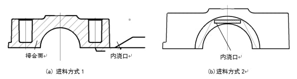
Two feeding methods are common (Figure 5). Method 1 feeds via the mating surface—simple to part, with gates removable by machining, but it causes uneven semicircle temperatures and poor shrinkage compensation. Method 2 feeds from the semicircle parting line, improving shrinkage in thick areas and temperature consistency, though it complicates mold parting and leaves gate marks. Method 2 suits machined semicircle ends; Method 1 fits unmachined ones. This study uses Method 2 for the 2JA-2 camshaft bracket.
Methods: Gating System Design and Validation
Using the 2JA-2 camshaft bracket (ADC12, 25 grams) as a case study, we designed a 1-mold-6-cavity setup on an 1800 kN machine. Here’s the process:
1. Initial Design
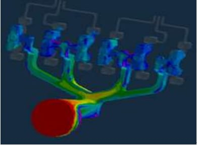
The first design used symmetrical runners (Figure 6), but simulation showed faster filling in central runners (Figure 7), disrupting pressure balance.
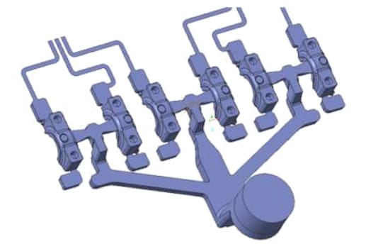
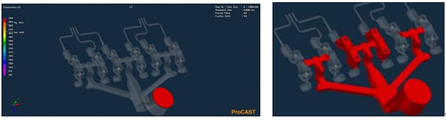
2. Improved Design
The revised system split the main runner into four branches, with the middle two splitting again (Figure 8). Deeper central gates controlled flow rates. Simulation (Figure 9) confirmed balanced filling and pressure.

3. Production Validation
Using a DM180 machine with a 50 mm plunger, parameters were: slow shot at 0.25 m/s, fast shot at 3.5 m/s, specific pressure at 80 MPa. X-ray inspection (Figure 10) showed 100% compliance with #2 standards and 90% with #1 standards across all cavities.
Results Table
| Standard | Compliance Rate | Notes |
|---|---|---|
| #2 | 100% | Meets client requirements |
| #1 | 90% | Minor variations |
Summary
Numerical simulation optimizes multi-cavity die-casting molds, reducing porosity and ensuring quality in small brackets. Consistent production requires tight control of mold and melt temperatures. This approach cuts trial time, lowers scrap rates, and boosts efficiency.