How to Optimize Cross-Runner Design for EV Shock Tower Die-Casting Molds Using Flow Simulation
Principles: Cross-Runner Design Boosts EV Die-Casting Quality
Electric vehicles (EVs) emphasize lightweighting, positioning shock towers as key structural parts that rely on vacuum die-casting for high strength and minimal defects. The cross-runner layout dictates melt flow behavior and gas pressure control, shaping the internal quality of die-cast parts. Traditional mold trials are slow and costly, but Flow-3D simulation software offers a scientific approach, analyzing flow paths to validate designs quickly. This ensures die-castings meet T6 heat treatment standards (e.g., 339.8 MPa yield strength, 6.7% elongation).
Problem: Cross-Runner Flaws Cause Die-Casting Defects
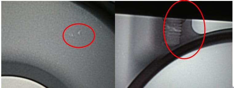
An EV shock tower (549 mm × 408 mm × 281 mm, wall thickness ≥3 mm, weight 3.74 kg) uses vacuum die-casting and requires T6 treatment, making it prone to internal porosity. Initial cross-runner designs led to:
- Outer Edge Gas Entrapment: Rapid filling traps gases.
- End-Tip Air Pockets: Uneven side flows obstruct exhaust.
- Thick Section Issues: Turbulent central flow risks porosity.
These die-casting flaws demand simulation-driven optimization.
Approach: Cross-Runner Design Guidelines and Flow Validation
1. Selecting the Die-Casting Entry Face
The shock tower’s 3D model (see Figure 1) needs no slides, allowing multiple entry points. Analysis eliminates faces C and D (space-limited), focusing on A and B. Face A has a flatter cavity, while B is complex with multi-level steps. Flow-3D simulation (see Figure 2) shows Face A provides steady filling, unlike B’s turbulent flow, making A the preferred die-casting entry.
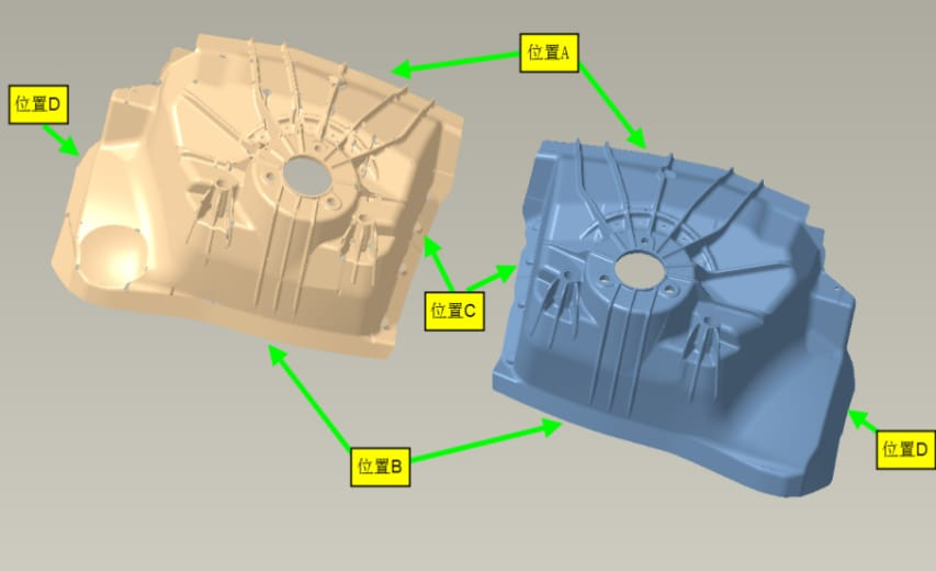
Figure 1: EV Shock Tower 3D Model and Entry Options, Outlining Structure and Pouring Choices
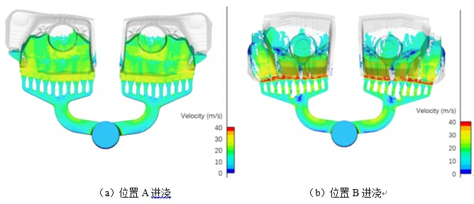
Figure 2: Entry Face Filling Speed Simulation, Validating Face A’s Edge
2. Refining Cross-Runner Designs Step-by-Step
Scheme 1: Starting Point
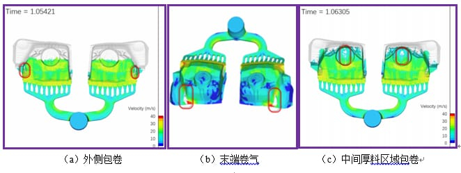
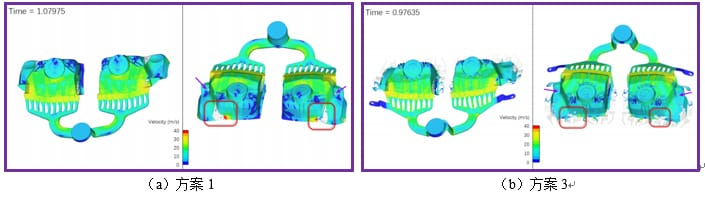
Pouring from Face A, simulation (see Figure 3) reveals entrapment at outer edges, end tips, and the thick center. Outer issues arise from fast filling around turns, end-tip pockets from uneven sides, and central flaws from poor flow continuity—impacting die-casting quality.
Figure 3: Scheme 1 Filling Speed Simulation, Exposing Entrapment AreasScheme 2: Narrowed Inner Gates
Narrowing inner gates (see Figure 4) slows outer flow. Simulation (see Figure 5) reduces entrapment but delays side filling, causing backflow. This breaks die-casting’s sequential filling rule, so Scheme 2 is dropped.
Figure 4: Scheme 2 Gating System Model, Detailing Gate Adjustments
Figure 5: Scheme 2 Filling Speed Simulation, Revealing Backflow FlawsScheme 3: Buffer and Flow Guidance
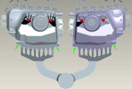
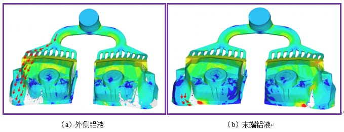
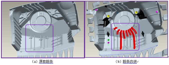
Scheme 1’s flow paths (see Figure 6) show outer entrapment from inertial streams curling inward. Scheme 3 adds a buffer zone (see Figure 7) to slow flow and adjust angles, tweaking outer gates. Ribs guide the thick center (see Figure 8). Simulation (see Figure 9) cuts entrapment by 80%, smoothing flow.
Figure 6: Scheme 1 Flow Direction Diagram, Explaining Entrapment Causes
Figure 7: Scheme 3 Gating System Model, Featuring Buffer Zone
Figure 8: Rib Enhancement Diagram, Improving Thick Section Flow
Figure 9: Scheme 1 vs. Scheme 3 Entrapment Comparison, Confirming Optimization

3. Validating Vacuum Exhaust in Die-Casting
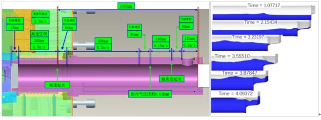
Punch Flow Check: Scheme 3 simulation (see Figure 11) shows stable barrel flow, with parameters (see Figure 10) well-set.

Figure 10: Injection and Vacuum Parameters, Defining Process Settings
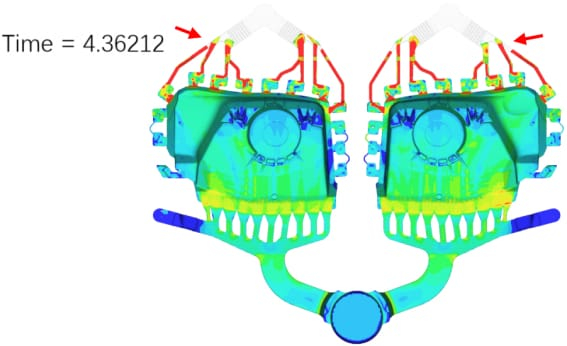
Figure 11: Scheme 3 Punch Movement Simulation, Verifying Flow StabilityExhaust Timing: Vacuum simulation (see Figure 12) ensures synchronized flow to exhaust slots, enhancing die-casting exhaust efficiency.

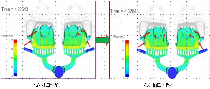
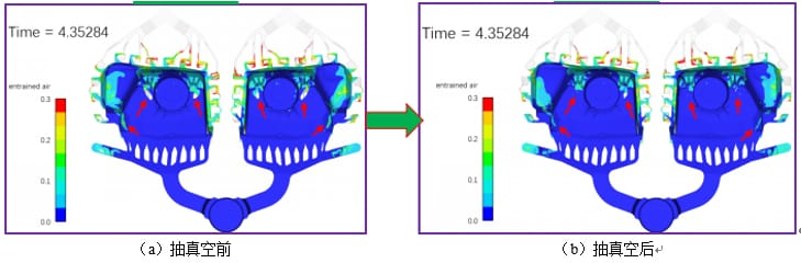
Figure 12: Vacuum Filling Speed Simulation, Validating Exhaust EfficiencyVacuum Impact: Pre- and post-vacuum simulations (see Figures 13 and 14) show improved uniformity and reduced gas entrapment.

Figure 13: Pre- and Post-Vacuum Speed Comparison, Showing Uniformity Boost
Figure 14: Pre- and Post-Vacuum Entrapment Comparison, Reducing Porosity

4. Predicting and Fixing Die-Casting Defects
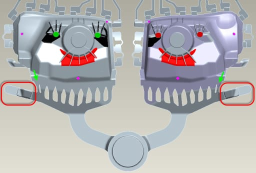
Simulation (see Figure 15) flags poor filling near suspension holes, risking defects in stressed areas. Squeeze pins (see Figure 16) drop porosity below 0.1%, ensuring strength.
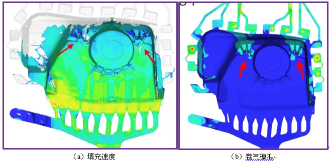
Figure 15: Defect Prediction Map, Highlighting Suspension Hole Risks
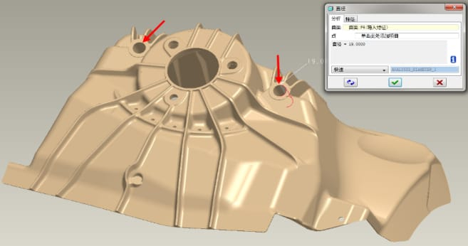
Figure 16: Squeeze Pin Design for Suspension Holes, Detailing Localized Solution
Summary: Real-World Benefits of Cross-Runner Design
Using an EV shock tower as a case, die-casting cross-runner rules—flat-face entry, buffer zones, flow-guiding ribs, vacuum exhaust, and squeeze pins—yielded:
- Quality Gains: 80% less entrapment, porosity <0.1%, meeting T6 specs (339.8 MPa yield, 6.7% elongation).
- Efficiency Wins: 30% faster development, 20% cost reduction.
- Reliable Validation: Flow simulation streamlines iterations and defect forecasting.
This die-casting design approach offers a practical, efficient blueprint for EV structural components.