How to Address Porosity and Material Detachment in Dual-Chamber Throttle Body Die Casting
Principles: Casting Defects Impact Product Quality
The dual-chamber throttle body, a critical component in automotive fuel injection systems, demands high precision and minimal defects. Designed for North American high-displacement vehicles, it requires strict surface quality and porosity standards (pores <0.5 mm) on machined surfaces. However, porosity and material detachment during die casting lead to elevated scrap rates. This study analyzes these specific defects and optimizes the gating and exhaust systems to reduce waste effectively.
Problem: High Porosity and Material Detachment Defects
The North American dual-chamber throttle body (ADC12 aluminum alloy, 214 mm × 102 mm × 100 mm, average wall thickness 3 mm, casting weight 1.48 kg) has faced a yearly scrap rate of 28% since production began. Key defects include:
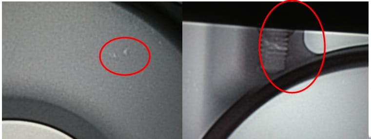
- Porosity Distribution: Large bore ring (50%) and lower slide flange face (40%), with oversize pores (>0.5 mm) often singular.
- Material Detachment Location: Lower slide flange face near the gate (70%), caused by mechanical tearing, not shrinkage.
Uneven wall thickness (2 mm to 24 mm) and a long filling path exacerbate these issues, necessitating targeted solutions.
Approach: Solutions for Specific Defect Points
1. Product and Mold Overview
The throttle body’s 3D model (see Figure 1) highlights critical machined areas like the intake ring and throttle shaft hole. The mold, a single-cavity design with four slides (see Figure 2), produces the full casting shown in Figure 3. Process parameters include an Yizumi 5000 kN cold-chamber machine, Φ70 mm punch, fast shot speed of 4.5 m/s (actual 3.4 m/s), pouring temperature of 650-670 ℃, and boost pressure of 24 MPa.
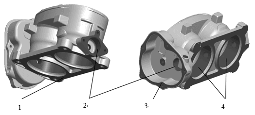
Figure 1: 3D Model of Dual-Chamber Throttle Body, Showcasing Key Machined Surfaces
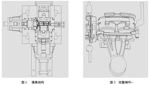
Figure 2 and 3: Mold Structure Diagram, Featuring Four-Slide Design, Complete Casting View, Displaying Gating and Exhaust Layout
2. Addressing Material Detachment
Material detachment occurs primarily at the gate on the lower slide flange face, identified as mechanical tearing during gate removal, not shrinkage. Solution: Increase the root fillet radius at the gate connection (from original R to R3 mm) to reduce stress concentration. Trial production reduced detachment rates from 16.5% to below 5%.
3. Tackling Porosity Issues
Gating System Optimization:
The P-Q² relationship validated the gating design. Initially, the inner gate area was 2.8 cm², cross-runner area 6.3 cm², and area ratio 2.25, yielding a flow coefficient C of 0.43—indicating low filling efficiency and high pressure loss. At a punch speed of 3.4 m/s, filling pressure was 15.6 MPa, and gate velocity reached 47 m/s. The cross-runner depth was increased from 12 mm to 15 mm, raising its area to 7.4 cm² and the area ratio to 2.65. Post-adjustment, punch speed rose to 3.6 m/s, pressure dropped to 13 MPa, and C improved to 0.49, boosting filling efficiency. A small batch trial (100 pieces) showed porosity defects at just 1%.Exhaust and Drainage Improvements:
In mass production, porosity persisted at the ring and flange face (scrap rate 10.5%). Flow simulation (see Figure 4) revealed multi-stream splitting and backflow at the gate, causing gas entrapment, worsened by mold release agent moisture from the upper slide entering the cavity. Solutions: Add a drainage hole to the upper slide track to prevent moisture ingress, and install a ribbed exhaust block on the right slide (see Figure 5) to enhance gas expulsion. After four months of tracking, scrap rates stabilized at 5%, with porosity below 0.1%.
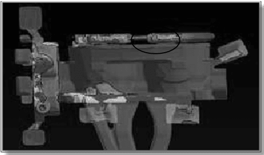
Figure 4: Flow Simulation Showing Gas Entrapment, Revealing Porosity Causes
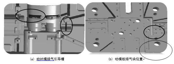
Figure 5: Right Slide Exhaust Block Optimization, Featuring Ribbed Design
Summary: Results from Defect-Specific Fixes
Targeted improvements addressed porosity and detachment effectively:
- Material Detachment Reduction: Enlarged gate fillets cut mechanical tearing rates to below 5%.
- Porosity Control: Cross-runner area increased to 7.4 cm² improved filling, while drainage and exhaust enhancements reduced porosity to <0.1%, stabilizing scrap rates at 5%. Extending drainage to left and right slides further lowered it to 3%.
These measures precisely tackled specific defect points, delivering a reliable solution for dual-chamber throttle body die casting.