How to Fix Vacuum Valve Failures in Aluminum Die Casting Exhaust Systems
Principles: Vacuum Die Casting for Enhanced Part Quality
Aluminum alloy die casting excels in precision, surface quality, and efficiency, yet high-speed mold filling often traps gases, forming porosity that compromises mechanical properties post-solidification. Vacuum die casting minimizes gas entrapment by filling molds in a vacuum, improving internal quality and gaining widespread use in the industry. However, mechanical vacuum valves, despite their large exhaust area and high vacuum levels, face challenges from molten aluminum’s inertial impact, causing valve core blockages or fractures that degrade vacuum performance. This study uses simulation and deceleration structure optimization to address these issues.
Problem: Vacuum Valve Core Blockages and Fractures
For an oil cooler bracket (411 mm × 214 mm × 191 mm, 4 mm wall thickness, 3.4 kg), the exhaust system employs a mechanical vacuum valve. Production reveals valve core blockages at the head (A) and fractures at the tail (B). Anycasting simulation shows molten aluminum reaching the valve at ~68 m/s, a velocity high enough to cause these failures, necessitating a solution to reduce impact.
Approach: Deceleration Structure Design and Validation
1. Initial Design and Problem Analysis
The oil cooler bracket’s gating and exhaust system (see Figure 1) features a 765 mm² gate area, 265 mm² exhaust area, and Φ100 mm punch diameter. The vacuum valve core (see Figure 2) suffers head blockages from high-speed aluminum scouring (A) and tail fractures from stress concentration (B). Simulation via Anycasting’s AnyPRE module (see Figure 3) confirms a velocity of 68 m/s at the valve, linking excessive impact to the issues.
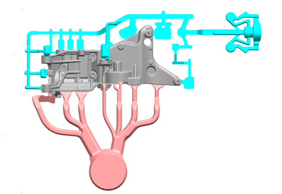
Figure 1: Oil Cooler Bracket Gating and Exhaust System, Showcasing Initial Design

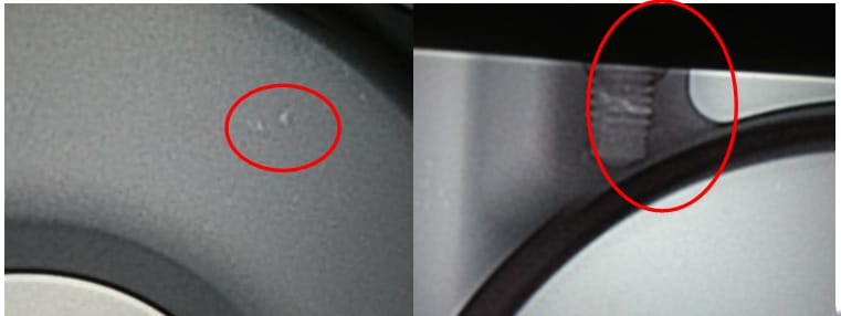
Figure 2: Vacuum Valve Core Structure Diagram, Highlighting Blockage and Fracture Zones
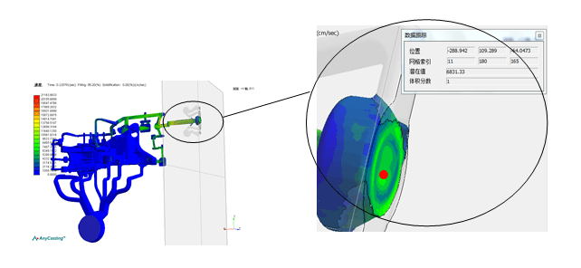
Figure 3: Original Scheme Velocity Simulation, Showing 68 m/s at Valve
2. Deceleration Structure Optimization
A deceleration structure is added at the exhaust channel’s end to slow the aluminum flow. Options include triangular, circular, diamond, square, and concave-convex designs (see rests in Table ).
A triangular structure is selected, with the modified system shown in Figure 4. Simulation with identical mesh and parameters (see Figure 5) reduces the velocity to 29 m/s, cutting impact force significantly.
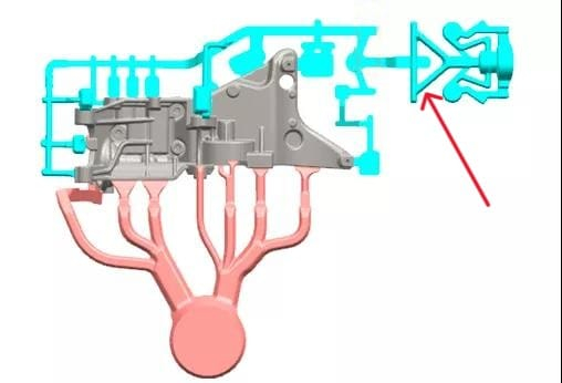
Figure 4: Modified Gating and Exhaust System, Featuring Triangular Deceleration Structure
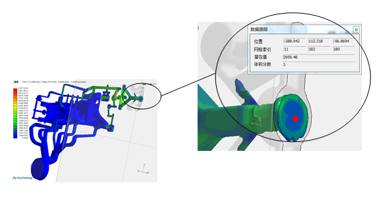
Figure 5: Optimized Scheme Velocity Simulation, Verifying 29 m/s at Valve
3. Implementation and Results
Mold modifications implement the triangular structure. Post-trial, no valve core blockages or fractures occur, lifespan improves, vacuum stability enhances, and porosity drops below 0.1%.
Summary: Practical Benefits of Deceleration Structures
Adding a triangular deceleration structure at the exhaust channel’s end reduces aluminum velocity from 68 m/s to 29 m/s—a 57% drop—lowering impact force by approximately 57%. This eliminates valve core blockages and fractures, extends service life, and boosts casting quality, offering a practical fix for vacuum die casting exhaust systems.