Integrating a motor end cover with a gearbox into a single aluminum alloy die-cast part transforms small, low-speed motors—boosting strength, precision, and cost-efficiency. This case study explores the mold design for such a component, merging two traditionally separate pieces into one. By tackling inefficiencies of split designs, we’ll uncover a side-gate mold solution that’s simple, reliable, and primed for mass production.
Problem: Pitfalls of Traditional Split Designs
Small motors often run at 960 RPM, but applications needing speeds in the dozens require a gearbox. Conventionally, the motor end cover and gearbox are cast separately, with the motor shaft turned into a worm that meshes with a turbine inside the gearbox. Screws then join the two. Sounds straightforward, right? Not quite. This setup hit three snags:
- Loose Connections: Long-term vibration loosened screws, risking failure.
- Cost Overload: Two molds doubled material and fastener costs.
- Assembly Hassles: Aligning separate parts ate time and precision.
These issues screamed for a rethink—could one die-cast part solve it all?
Approach: A Unified Mold Design Strategy
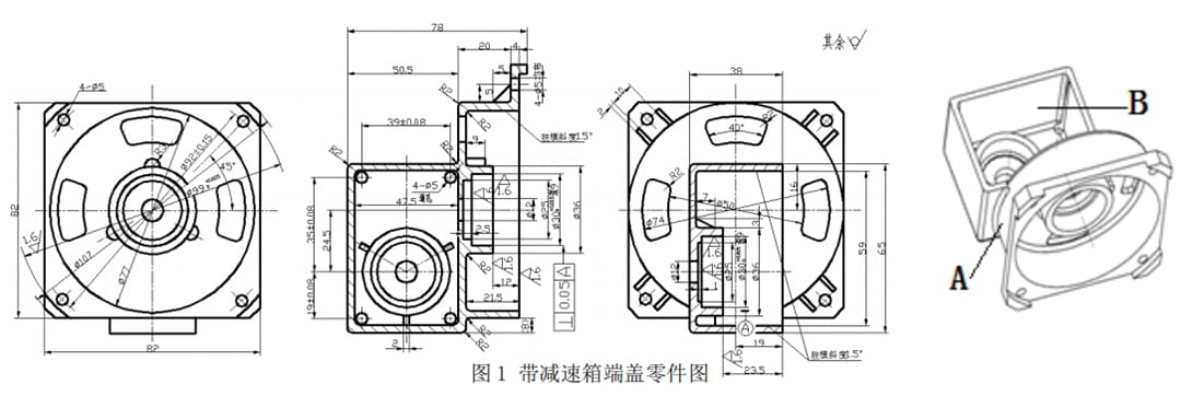
To ditch the split design, the team merged the end cover and gearbox into a single casting (Figure 1). The mold design needed to:
- Analyze Geometry: Map the part’s quirks for gating and core placement.
- Optimize Gating: Balance fill efficiency with easy waste removal.
- Manage Clamping Force: Break down ejection resistance smartly.
The goal? A mold that’s sleek, effective, and delivers clean castings at scale.
Methods: Crafting the Mold Solution
Mold Structure
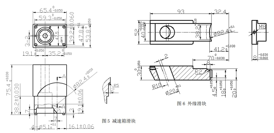
The mold (Figure 2) pairs a fixed platen with a moving one. Key players include the fixed core (end cover), moving cavity (gearbox), gearbox slider (with bearing core), and outer-edge slider. A side gate at the end cover-gearbox junction (A in Figure 1) ensures smooth filling and easy waste trimming. Sliders at the gearbox cavity (B) and outer edge handle complex shapes.
Alt: Die-casting mold assembly for integrated motor end cover and gearbox
How It Works
Molten aluminum flows through the sprue sleeve, driven by the injection punch into the moving cavity. After cooling, the mold opens. First, the fixed and moving platens part horizontally, with a 2 mm gap between angled pins and sliders delaying core pull. This frees the casting from the fixed core. Then, gearbox and edge sliders retract along angled pins, fully releasing internal features. Five ejector pins—including one for sprue waste—gently push the casting out.
Alt: Ejection process in die-casting mold for motor end cover and gearbox
Design Wins
- One-Piece Perks: Merging parts boosts strength, cuts molds, and skips fasteners.
- Side-Gate Smarts: Fills cleanly and simplifies waste removal.
- Upside-Down Logic: Fixed core on the end cover, sliders on the gearbox side leverage resistance to keep the casting in the moving cavity—ejection’s a breeze.
- Pin Placement: Four 6 mm pins at 5 mm mounting holes ensure even push-off, hiding marks neatly.
Why It Shines
The side-gate choice tackled fill and cleanup in one go. Sliders split clamping force across two zones—gearbox and edge—easing release. Three arc-shaped cooling slots (Figure 1) got simple raised bosses on the fixed core, dodging tricky inserts. It’s a design that thinks ahead.
Conclusion: A Mold That Delivers
This integrated mold swaps split-design woes for a unified win. Side gates and strategic sliders nail filling and ejection, slashing costs and boosting reliability. For complex die-cast parts, it’s a blueprint worth borrowing—smart, scalable, and spot-on. Want to see how this casting gets polished to perfection? Check out our companion piece, “Post-Processing and Fixture Design for Integrated Motor End Cover and Gearbox Die-Casting,” for the next step in turning raw castings into precision components.
Key Features Table
| Feature | Detail |
|---|---|
| Part Size | End cover + gearbox combo |
| Gating Type | Side gate |
| Slider Count | 2 (gearbox, outer edge) |
| Ejector Pins | 5 (4 at 6 mm, 1 for waste) |
| Core Placement | Fixed (end cover) |