Porosity in Aluminum Alloy Die-Casting Engine Blocks: Causes and Solutions
Porosity Formation Principles
Porosity in aluminum alloy die castings falls into two types: precipitation porosity and entrapped porosity. Precipitation porosity arises from high melting temperatures (>750°C) increasing hydrogen solubility in the melt, or from slag-heavy revert material with poor deslagging. Entrapped porosity stems from process or design flaws, such as low shot sleeve fill ratios, premature high-speed injection, excessive mold release agent gas, or poorly designed gating and venting systems, trapping gas in the melt. These pores are typically smooth-walled and round, appearing at casting ends or complex areas.
Alt: Diagram illustrating precipitation and entrapped porosity formation in aluminum alloy die casting.
Problem Description
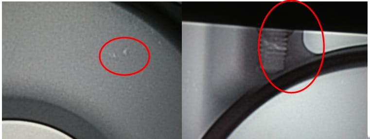
An 8.5kg ZL201 aluminum alloy engine block, cast on a Buhler 28,000kN cold-chamber machine, showed random porosity on its marking surface via X-ray and machining checks. In 2017, the porosity rejection rate hit 2.5%, with smooth, dark gray pores threatening sealing and strength—unacceptable per technical specs.
Alt: X-ray image showing porosity distribution on the engine block marking surface.
Solution Approach
Porosity results from melt quality, process parameters, and mold design. Precipitation porosity can be curbed by refining melting practices, while entrapped porosity ties to filling dynamics. The strategy involved tackling process settings, melt purity, and gating design step-by-step to pinpoint and eliminate key causes.
Solution Methods
Process Parameter Adjustments
Issue: High-speed injection started at 500mm (reasonable), but complex cavities trapped gas; post-spray mold temperature was 120°C—below the ideal 160-190°C—causing excess release agent gas.
Fix: Delayed high-speed start to 510mm, reduced spray time from 1.5s to 1s, and added 0.5s air blow, raising mold temperature to 160°C.
Result: Rejection rate dropped from 2.5% to 2.3%—modest progress.
Melt Process Optimization
Issue: Revert material exceeded 50% with poor cleanliness, raising hydrogen content (density 1.523).
Fix: Pre-dried revert limited to 30%-45%, degassing time extended from 260s to 300s.
Result: Hydrogen density fell to 0.927, reducing rejection rate to 2%—still insufficient.
Gating System Improvements
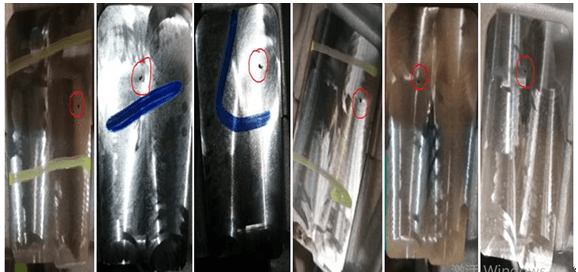
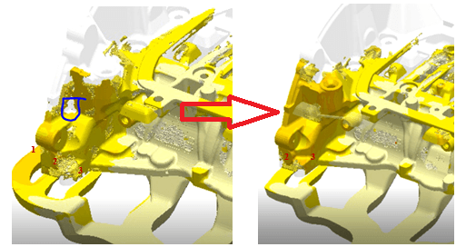
Issue: Gating design caused turbulent filling and gas entrapment at the marking surface (Figure 3).
Fix: Mold flow analysis guided changes: sealed Gate 1, widened Gate 2 by 3mm, narrowed Gate 3 by 3mm.
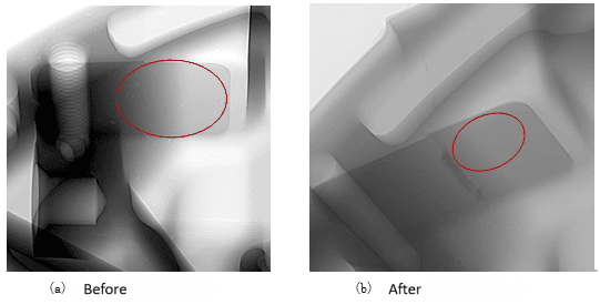
Result: Improved filling eliminated entrapment (Figure 4), cutting marking surface rejection rate to 0.12%.
Alt: Mold flow analysis showing optimized melt filling sequence after gating adjustments.
Alt: X-ray comparison of porosity on the marking surface before and after improvements.
Improvement Summary Table
| Stage | Issue Identified | Action Taken | Rejection Rate |
|---|---|---|---|
| Process Parameters | Early high-speed, low mold temp | Delayed start, adjusted spray/blow | 2.5% → 2.3% |
| Melt Optimization | High hydrogen in melt | Cleaner revert, longer degassing | 2.3% → 2.0% |
| Gating Redesign | Turbulent filling | Sealed Gate 1, resized Gates 2 & 3 | 2.0% → 0.12% |
Conclusion
Porosity in the engine block arose from hydrogen in the melt and gas entrapment during filling. Initial tweaks to process and melt reduced defects modestly, but gating redesign via mold flow analysis proved decisive, slashing the rejection rate from 2.5% to 0.12%. This step-wise approach offers a practical blueprint for tackling similar porosity issues in die casting.